Optical fibre

If we look back at the old days, we’d find that the internet speed was
incomparable to nowadays’ speeds and clock rates, this is because of new
technologies that succeeded to apply optical fiber networks rather than the old copper-based
networks.
Actually, If we tried to concentrate more we’d find that today’s internet
and computer networks depends totally on communication systems and
transmission of data using physical networks consisting of copper-based
wires or optical fiber cables.
The importance of optical fiber networks was highlighted when data has
grown enormously, and the demand on high performance and applications such
as online games and freelancing, etc. All of this caused users to need much
more bandwidth to exchange, upload, and download data. And this can’t be
done without a stable and powerful network.
Copper cables always used to have a bottleneck when it came to bandwidth
and long-distance data transmission. At this point we had to find more
powerful cables that’s capable of carrying more bandwidth at higher speed,
which is I’m going to demonstrate in this article.
Here is a quick comparison between copper cables and optical fiber cable,
in terms of data transmission:
|
Parameter |
Fibre Optics |
Copper |
|
Bandwidth |
60 Tb/s and beyond |
10 Gb/s |
|
Distance |
19 Metre+ @ 10,000Mbps |
90 Metre. @ 1,000Mbps |
|
Noise |
Immune |
Susceptible to interference, crosstalk and voltage surges |
|
Security |
Nearly impossible to tap |
Susceptible to tapping |
|
Handling |
Lightweight, thin diameter, strong pulling strength |
Heavy, thicker diameter, strict pulling specifications |
|
Lifecycle |
30-50 Years |
5 Years |
|
Weight/300 ft. |
1.8 kg. |
18 kg. |
|
Energy Consumed |
2W per User |
>10W per User |
The basic advantage that makes an optical fiber cable dominate a copper
cable is its speed. As we all know that the speed of light is the highest
speed in our universe according to Einstein’s relativity, with a constant
speed of 300 000 km/s in vacuum, compared to the speed of an electron
through a conductor is around 2200 km/s, we find that there is a huge
difference, and if we could find a system that depends on the speed of light
to transmit data there would be a big movement in the world of data
transmission and communication, which is simply “Optical fiber cables”.
As we’ve mentioned above, an optical fiber cable depends on the speed of
light, which means simply that it conveys light signal.
The basic components of an optical communication system are:
Advantages of Fibre Optics over copper cables

2- Lower signal attenuation (loss).
3- No crosstalk.
4- Lower bit error rates.
5- difficult to tap.
6- No electromagnetic interference
7- Immunity to Electrical fields
8- Reduced size and weight cables
9- Environmental Protection
10- Resistant to radiation (gamma radiation) and corrosion
11- Resistant to temperature variant
12- Low cost
Applications of Optical Fibre
1- Computer networks
2- Telephone lines
3- Medical applications
4- Submerged communication
5- Power station
6- Military application
The nature of light
Light is usually described in one of three ways:
1- Rays
In the classical physics that many of us learned at school, light consisted
of “rays” that could be reflected and refracted through mirrors and prisms
etc. This is a good description as far as it goes but it cannot explain many
of the phenomena we make use of in optical communications.

2- Photons
In many contexts light behaves as though it consists of tiny particles
called
“photons”.
3- Electromagnetic Waves
All light is a form of electromagnetic energy. But, what is electromagnetic
energy? Electromagnetic energy is emitted by any object that has
a temperature above absolute zero (–273° C), which means that
the atoms in the object are in motion. The electrons orbiting
the atoms pick up energy from the motion, and the energy causes
them to move to higher orbits, or energy levels. As they drop
back to their original energy levels, they release the energy
again. The energy takes two forms: an electrical field and a
magnetic field, formed at right angles to each other and at
right angles to their path of travel, as shown in the Figure

The wavelengths most commonly used for fibre optics are in the
infrared range, with values of 850 nm, 1310 nm, and 1550 nm.
The spectrum range of these wavelengths provides an important combination
of characteristics:
it is high enough to make high data rates possible, but
low enough to require relatively low power for transmission
over long distance.

Those specific wavelengths have been chosen as they provide the highest
data rates at the lowest power consumed.
The speed of light in a medium depends on the refractive index of that
medium, we find that speed of light is changeable depending on the
medium
v = c/ n
Where:
n is the refractive index of the material.
c is the velocity of light in vacuum.
v is the light’s velocity through the material.
And this figure shows light speed through different mediums

Optical fibre structure:
But what actually the structure of an optical fibre cable?
An optical fibre cable consists of three components:
1- Core.
2- Cladding.
3- Cover.
· The core can be thought of as a very long solid rod made of glass.
· The cladding is a cover wrapped around the core and it’s also made of
glass, with a refractive index smaller than the core.
· The cover is a protection layer made of plastic to protect outer dust,
liquids, and lights.

Notice that the index of the cladding is larger than the index of the
cladding. And the figure shown only shows the core and the cladding without
the cover.

The critical angle:
As shown in the above figure, the critical angle is the angle by which the
light beam should be directed towards the core at the beginning of the cable
to stay having total internal reflection, this angle can be calculated
by:
θc = arcsine(n2 ÷ n1)
example: if we want to know the critical angle of an optical fibre having a core RI
of n1 = 1.51 and a cladding RI of n2 = 1.46:
θc = arcsine(1.46 ÷ 1.51) = 75.211°
Types of Optical fibres:
1- Single-mode Optical Fibres:
Single mode is a type of optical fibres used for connecting in long
distances. And from the name it has only single mode (one beam of light with
single wavelength) the advantages of single-mode optical fibres are as
follow:
1- It’s used for transmission and communication between different
exchanges.
2- It’s used for long distances as it has less attenuation than
multi-mode.
3- It carries a single beam of light.
4- The device that produces that beam of light consists basically of a laser
diode, and that’s why it’s a single mode.
5- The diameter of a single-mode fibre is 250 μm with a core of 9 μm, a cladding of 125 μm, and a cover of 250 μm.
2- Multi-mode Optical Fibres:
Multi-mode optical fibres usually used for short-distance connection, and
as illustrated in single-mode it can has multiple modes (beams of light with
multiple wavelengths), and the advantages of multi-mode optical fibres
are:
1- It’s used for transmission and communication only in short distances such
as between the cabinet and the client, usually less than 2 kilometres.
2- It’s used for short distances as it has more attenuation than
single-mode.
3- It can carry multiple beams of light with multiple wavelengths.
4- The device that produces those beams of light mainly consists of LED(Light
Emitting Diode).
5- The diameter of a single-mode fibre is 250 μm with a core of 50-62 μm, and a cover of 250 μm.
Attenuation
There are three reasons that cause attenuation inside of an optical
fibre:
1- Absorption
All materials, even the clearest glass, absorb some light. The amount of
absorption depends on the type of material and the wavelength of the light
passing through it.

2- Scattering
Scattering is caused by atomic structures and particles in the fibre
redirecting light that hits them, as shown in Figure

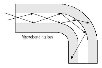
3- Bending Losses
· Micro bending

· Macro bending
Total Attenuation
Total attenuation is the combination of the effects of absorption and
scattering in a fibre.
First, we should define Attenuation, Attenuation in optical fibres means
the loss of power depending on different parameters along the cable from the
exchange to the client.
Let’s take some parameters, by which we lose power along the route:
1- Every splicing point has an approximate attenuation of 0.1 dB
2- The attenuation per kilometre depends on the wavelength that we’re using,
for instance:
· If we’re using 1310 nm : the attenuation per kilometre = 0.35 dB
· and if we’re using 1550 nm : the attenuation per kilometre = 0.25 dB
3- Every 4 kilometre we must have a splicing point, because fibre optics
rollers is made with a length of 4 kilometres, therefore we must have a
splicing point every 4 kilometres.
4- Every connector on the fibre has a maximum attenuation of 0.5 dB
5- Each ODF (Optical Distribution Frame) has an attenuation of 3.5 dB
6- Finally, every splitter has an attenuation depending on input ports :
output ports, for instance:
· 1 : 2 splitter has an attenuation = 3.5 dB
· 1 : 4 splitter has an attenuation = 7 dB
· 1 : 8 splitter has an attenuation = 10.5 dB
· 1 : 16 splitter has an attenuation = 14 dB
· 1 : 32 splitter has an attenuation = 17.5 dB
The sum of all of those attenuation values gives us the total attenuation
on the network along the cable.
Fibre optic connector components
The job of a fibre optic connector is to couple a fibre end mechanically to
a piece of hardware or to another fibre so that the cores line up accurately
and produce the smallest amount of loss.

Geometry
Geometry refers to the shape of the ferrule endface as shown:

And there are many types of connectors based on the geometry, and body and cap size.
Here are the different types of optical fibres’ connectors:

Optica fibres splicing
When we splice two optical fibre cables we should make sure that the two
filaments to be spliced have the same characteristics in terms of the core
and cladding diameter, the overall diameter, the refractive indexes are the
same, and the most important thing, that they should be regular (cleaved
with 90 degree angle on the centre line of the cable) and clean from dust
and smoke.
Optical fibres stripper
This equipment is used to strip the optical fibre filaments and remove the
cover layer of the two different fibres to be spliced.

Optical cleaver
This equipment is used to cleave the two terminals of the two filaments to
be spliced precisely with no cleaving angles, and no bad cleaving.

And here is how cleaving can be:

The cleaved part after the cover layer should be around 20 mm to 15 mm.
Splicing Equipment
The goal of any optical fibre splice is to join two fibre ends permanently
with as little loss in optical quality as possible.
Optical fibres may be spliced using two methods: mechanical splicing and fusion splicing.
Mechanical Splicers
Mechanical splicers use a plastic tube with a locking mechanism that holds
two fibres against each other to make a splice as shown in fig.

The two spliced terminals are hold forever in the shown fixture
mechanically.
This way of splicing has more attenuation than fusion-base splicing and
mechanical splicers are usually inexpensive but has less features.
Fusion Splicers
Fusion splicers create a permanent splice by welding the fibre ends to one
another
with an electrical arc. The splice is then enclosed in heat-shrink tubing
with an
oven built into the splicer. The following figure shows a fusion
splicer:

Fusion splicers are usually expensive and cost thousands of dollars, they
have much more features than mechanical splicers, they have an automatic
mechanism to align the two fibre ends, they have high resolution images and
videos for the two ends while splicing, and they can calculate the value of
attenuation after splicing as shown.

Splicing Procedures
As fusion splicing is much more effective than mechanical, precise, and
common when it comes to single-mode and long-distance communication
networks, we’re going to illustrate its procedure in detail:
Fusion Splicing Procedure
Many fusion splicers contain a feature that automatically positions the
fibre ends in
proper relationship with each other and with the electrodes for the best
possible
splice. All that is required of the operator is to prepare the fibres
properly and place
them in the device.
To prepare for fusion splicing, as with mechanical splicing, make sure that
the
work area is clean, dry, and well-lit. Assemble the following tools before
you
begin:
- Fusion splicing tool
- Plastic coating stripper
- Reagent grade isopropyl alcohol
- Lint-free wipes
- Cleaver
- Heat-shrink tubing
Once your materials are assembled, proceed with the following steps:
Set-up
1. Open the fibre buffer tubes and expose and clean the fibres.
2. Enable power to the fusion splicer.
Fibre Preparation
3. Remove from the storage reel or coil the minimum length of fibre
required to
prepare and splice the fibres—less than one loop if possible.
4. Slide the heat-shrink tubing over one fibre end and move it far enough
up the
fibre to place it out of the way.
5. Strip approximately 1 to 2 inches (25 mm to 51 mm) of plastic coating
from the
fibre using a mechanical stripper.
6. Clean the bare glass by pulling the fibre through an alcohol soaked
lint-free
wipe. This removes any fragments or dirt remaining on the fibre.
7. Cleave the fibre to the length specified by the brand of splicer you are
using,
typically 12–14 mm ± 0.5 mm. Note: The cleaved ends should be within 2°
of
perpendicular to the fibre axis and should be free of defects.
Splice Assembly
8. Position one fibre end in the unit near the electrode and close the
fibre clamp
next to the electrode.
9. Close the outer clamp on the fibre.
10. Repeat steps 7 and 8 for the other fibre end to be spliced.
11. Close the electrode cover.
12. Select the appropriate splicing program in the splicer’s computer
control and
activate it. The splicer performs the necessary calibrations and
positioning,
performs the splice, and measures the loss across the splice. The operation
may
be viewed through the video monitor, if available, as shown in Figure

Optical fibre measurement
Visible Fault Locator
The VFL can be separated or built-in an OTDR (Optical Time Domain
Reflectometer). It’s a device that injects a beam of light inside the fibre
to track the changes of the beam and locate the micro bendings, or breaks as
shown in figures:


OTDR (Optical Time Domain Reflectometer)
Information that can be measured
1 - The attenuation.
2 - The location of faults, by their distance from a point of origin.
3 - Attenuation with respect to distance (dB/km).
4 - The reflectance of a reflective event or a link.
The aim of this instrument is to detect, locate and measure events at any
location in the fibre link.
The OTDR depends on the phenomena of scattering of light inside of an
optical fibre and generates a relation that describes the behaviour of light
inside of the fibre according to relation between the attenuation and the
distance as shown:

When the light reaches the end of the cable, it makes this oscillation that
appears at the end of this plot, referring that it’s the end of the fibre
cable.
Plesiochronous digital hierarchy
In the early 1970s, digital transmission systems began to appear, utilizing
a method known as Pulse Code Modulation (PCM), first proposed in 1937. PCM
allowed analog waveforms, such as the human voice, to be represented in
binary form.
Principles of PDH Multiplexing
PDH signals with a higher transmission rate are obtained by multiplexing
several lower rate signals.
Multiplex Operation
Four input signals with the same nominal bit rate are combined to form one
multiplex signal and then relayed to the receive side via one common
transmission path.
De-multiplex Operation
On the receive side, the sum signal is again distributed to the
corresponding outputs.

the above figure shows the multiplexing process of CEPT, the standard
method of European multiplexing.
As we shown, the term PDH is an abbreviation for Plesiochronous Digital
Hierarchy, it’s a frame that uses a combination of electronic circuits to
send data as bit patterns of zeros and ones, it uses a channel of a rate of
1/8000 second to send data, and consisted of 32 slot every slot has 8 bits,
and if we put all that together we will find that (8000 sec * 32 slot * 8
bit = 2.048 Mb/s) which is the clock rate of this frame.
By multiplexing frames with bit rate of 2.048 Mb/s we will be able to get
higher rate of PDH as shown in figure.
This operation should be done at the send side, but when it come do the
receive, there should be a reverse operation of demultiplexing to read
data.

This is the system used by CEPT to get high transfer rate Each
bidirectional arrow stands for a PDH frame.
Frame Structure of a PDH Signal
Every signal within a CEPT hierarchy level has a specific frame structure
which basically consists of the following blocks:

This frame consists of 32 slot horizontally, each slot has 8 bits
vertically, and each bit can contain whether 1 or 0, it can make 30 calls at
the simultaneously.
Multiplexing / Demultiplexing of PDH Signals
Multiplexing in PDH can be done using bit-by-bit multiplexing as shown
below:

As shown the job of a multiplexer is to add the two frames in one frame,
this new frame should have a transfer rate of the sum of frames I and II
together. The CEPT standard managed to reach the highest rate using
multiplexing which is 140 Mb/s.
Disadvantage of PDH
There were actually some disadvantages of using PDH, first of all the lack
of flexibility, simply, we can’t extract a specific lower rate if we want
for instance, to provide a customer with a single 2 Mb/s channel. In order
to access a single 2 Mb/s line the 140 Mb/s channel must be completely
demultiplexed to its 64 constituent 2 Mb/s lines via 34 and 8 Mbit/s. Once
the required 2 Mb/s line has been identified and extracted, the channels
must then be multiplexed back up to 140 Mbit/s.
Another limitation of the PDH is its inability to provide different
Topologies, as it only can provide a very basic point-to-point topology.
Last limitation, it was not synchronous, and consequently it had some
issues when it came to multiplexing frames together, as the multiplexer
supposes that all its inputs are being operated at the same time, more
clearly, the last bit on the right inside every frame must be added to the
equivalent bit in the other frame. We could solve that by using a container
that has a bigger rate than all of the input frames, and this container’s
job is to stuff all the bits resulting from the difference between this
container and every frame, those bits are called stuffing bits, and PDH is highly dependent on stuffing bits. And this us another
issue, because stuffing bits are filled with nonsense which don’t have any
role at the demultiplexing end, except for the taking space inside of the
frame.
Synchronous Digital Hierarchy
The main feature of a Synchronous Digital Hierarchy system is the ability of being
synchronous, and this is a feature that PDH couldn’t achieve, as every frame in PDH
has its own clock rate, or in other words, it’s own clock generator, that’s
why PDH was suffering from different clock rates.
But if we could create a system that has a reference clock generator, we
would have a uniform clock rate for all frames to be multiplexed, therefore,
we’d be able to get rid of the stuffing bits.
Another advantage of SDH system, is its structure, it consists of 9 rows
every row has 270 slot, and each slot has a 8 bits. Therefore, the total
number of bits in SDH frame = 9 * 270 *8 = 19440 bit
So far so good, let’s now try to find the base rate of this frame. As
we know the frame is just like a PDH frame, it’s repeated 8000 per second,
so if we multiply the number of bits by 19440 * 8000 = 155.52 Mb/s.
The ITU (International Telecommunication Union) has specified a base
signal, the STM-1 (Synchronous Transport Module - 1) with 155,520 Mb/s. All
multiplex levels in the SDH are positive integer multiples of this base
signal "STM-1" as shown below:

Those simply are the rates of an SDH frame, beginning from the base rate,
going all the way up by multiplexing frames together.
Note: the STM-4 is 4 multiples of a STM-1 frame, likewise, the STM-64 is 16 multiple of STM-4 and vice versa.
Structure of an STM-1 Frame
The two-dimensional representation of an STM-1 frame includes 9
rows with
270 bytes each as shown:

The STM-1 frame consists of three blocks:

· Pointer (PTR): indicates the start address of the tributary
information.
· Section OverHead (SOH): additional transmission capacity.
· Payload: tributary information.
The “Section OverHead” and Pointer are for management, and the payload are
for data.
The frames are transmitted in intervals of 125 μs.
The STM-1 frame is repeated (1s: 125 μs) = 8000 times per second.
Thus, every byte in an STM-1 frame has a transmission capacity of 8000 * 8
= 64 kb/s, as we’ve cited before in the PDH frame.
Another advantage of SDH over PDH, that it uses byte-by-byte multiplexing,
in contrast to PDH that uses bit-by-bit multiplexing.
For a better understanding, the generation of an STM-4 frame was
explained here with only 2 STM-1 frames, although in practice 4 STM-1 frames
are multiplexed.

Byte-by-byte multiplexing.
Summary
Principles of PDH multiplexing
· Bit rates in accordance with CEPT: 2 Mbit/s, 8 Mbit/s, 34 Mbit/s and 140
Mbit/s.
· Every signal has a separate frame structure.
· PDH depends on Bit-by-bit multiplexing.
· No frame synchronization of the tributary signal inputs.
· The input signals of the tributaries are plesiochronous to each other, in
other words. their clock rates have the same nominal value, but there is,
however, a slight amount of variation between the two.
Principles of SDH multiplexing
· Bit rates exceeding 140 Mbit/s are standardized on a worldwide basis,
unlike PDH.
· Both synchronous and plesiochronous operation is possible.
· All current PDH signals (CEPT/ANSI) can be transmitted within the SDH
(except for 8 Mb/s).
· The "Section OverHead" bytes provide a high transmission capacity for
monitoring, maintenance and control tasks.
· High-level multiplex signals are integer multiples of the basic bit rate
(155,520 Mb/s).
· For the first time, the optical line code is standardized worldwide.
Comments
Post a Comment